25 Results
View results:
Sort by:

Wind direction plays a crucial role in shaping the outcomes of Computational Fluid Dynamics (CFD) simulations and the structural design of buildings and infrastructures. It is a determining factor in assessing how wind forces interact with structures, influencing the distribution of wind pressures, and consequently, the structural responses. Understanding the impact of wind direction is essential for developing designs that can withstand varying wind forces, ensuring the safety and durability of structures. Simplified, the wind direction helps in fine-tuning CFD simulations and guiding structural design principles for optimal performance and resilience against wind-induced effects.

In order to be able to carry out a pushover analysis, it is necessary to transform the determined capacity curve into a simplified form. The N2 method is described in Eurocode EN 1998. This article should help to explain what a bilinearization according to the N2 method involves.

Compliance with building codes, such as Eurocode, is essential to ensure the safety, structural integrity, and sustainability of buildings and structures. Computational Fluid Dynamics (CFD) plays a vital role in this process by simulating fluid behavior, optimizing designs, and helping architects and engineers meet Eurocode requirements related to wind load analysis, natural ventilation, fire safety, and energy efficiency. By integrating CFD into the design process, professionals can create safer, more efficient, and compliant buildings that meet the highest standards of construction and design in Europe.

Windbreak structures are special types of fabric structures which protect the environment from harmful chemical particles, abate wind erosion, and help to maintain valuable sources. RFEM and RWIND are used for wind-structure analysis as one-way fluid-structure interaction (FSI).
This article demonstrates how to structural design windbreak structures using RFEM and RWIND.

In RFEM 6 it is possible to define multilayer surface structures with the help of the “Multilayer Surfaces” add-on. Hence, if you have activated the add-on in the model’s Base Data, it is possible to define layer structures of any material model. You can also combine material models of, for example, isotropic and orthotropic materials.

This article will show you how to properly consider the connection between surfaces that touch each other on one line with the help of line hinges in RFEM 6.

The quality of the structural analysis of buildings is significantly improved when the soil conditions are considered as realistically as possible. In RFEM 6, you can realistically determine the soil body to be analyzed with the help of the Geotechnical Analysis add-on. This add-on can be activated in the model’s Base Data as shown in Image 01.
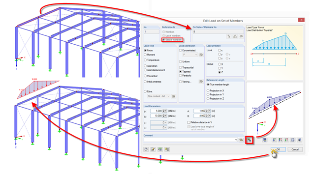
RFEM and RSTAB provide a helpful preview to check the input of member and line loads in the dialog box.

In RF-/STEEL EC3, sets of members are calculated according to the General Method (EN 1993-1-1, Cl. 6.3.4) together with the stability analysis. To do this, it is necessary to determine the correct support conditions for the equivalent structure with four degrees of freedom. In most 3D models today, you can quickly lose track of the location of a set of members in the system.
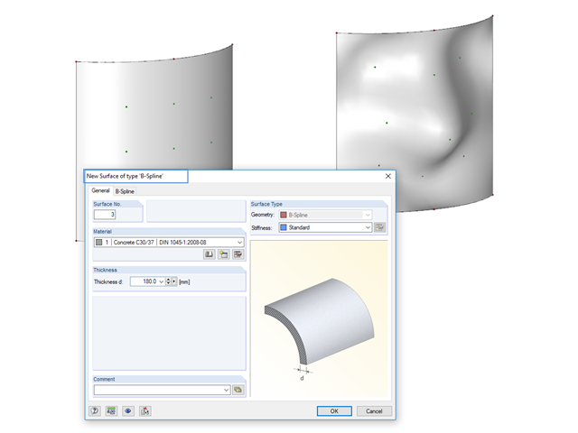
Instead of a quadrangular surface, you can use a B‑spline surface. The shape of this can be adjusted retrospectively, using the integrated help nodes. Depending on the necessary surface complexity, you can create a B‑spline surface with 3 × 3 or 4 × 4 help nodes.
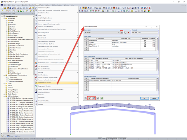
In RFEM and RSTAB, you can define a user-defined combination scheme. This can be helpful if a desired combination scheme cannot be created from a standard. In such cases, you can export the created load cases to Excel, create the scheme there, then import them to RFEM or RSTAB.
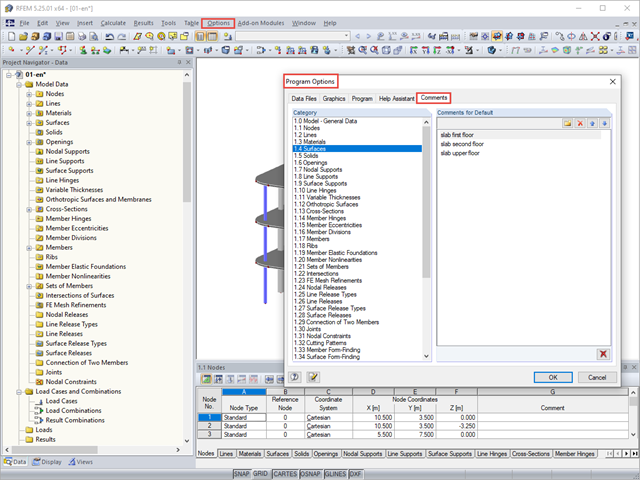
You can assign comments to each element in RFEM and RSTAB (structure element, load element, and so on). This can help to improve the overview and documentation of structures, as the comments appear in the printout report and, for example, certain objects can be filtered and displayed using the "Select Special" function.
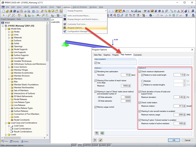
Under Options II in the Help Assistant tab of the program options, you can define the limit values for warning messages that appear after a successful calculation.
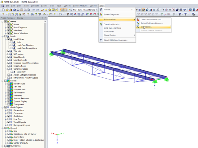
In RFEM 5 and RSTAB 8, you can view detailed information on the currently used license and installed dongle driver. In case of any problems with the license, you can send the created text file to the Dlubal Software hotline, which allows us to provide you with a fast and efficient analysis. To create the file, select "Help" → "Authorization" → "Diagnostics".
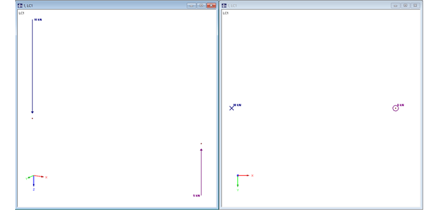
In RFEM, structures can be modeled and analyzed in a spatial environment. The permanent 3D visualization helps you to better understand complex models and to represent the force flux. However, you can switch from a spatial mode to a planar sheet mode in the documentation of a calculation. To do this, you have to describe the spatial calculation of the structure with all the necessary properties on "flat" paper pages for an independent reader. Usually, you try to display the load actions and the corresponding results by using an orthogonal view of the substructure of the entire structure. Obviously, the load symbols depicted in the 3D mode in a view perpendicular to the load become unrecognizable due the missing expansion. In order to be still able to create a clear representation of all information, the corresponding adjustments are available in RFEM.
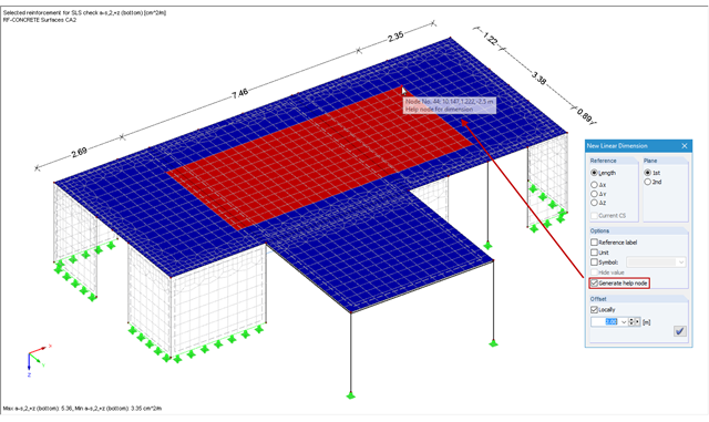
In RFEM and RSTAB, you can add user‑defined dimension lines to a structural model. When creating these dimension lines, click the objects (for example, end nodes of a line, members, and so on) that represent the reference points of the dimension. If you want to add a dimension line free from the structure previously defined in the model, you have to create an additional free "help node" that acts as a reference object for the new dimension.
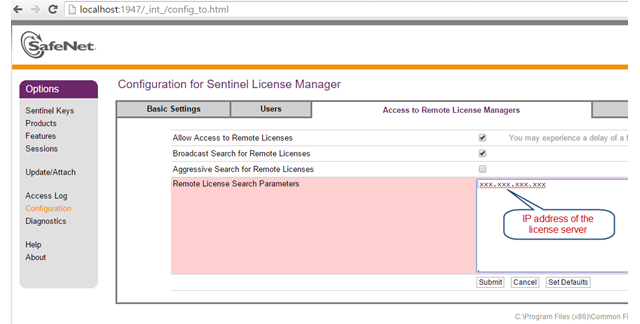
The network licenses of Dlubal Software provide a very convenient solution for engineering offices as well as for users who are often on the move. This can be helpful if you are in a consulting meeting with a building owner and want to directly apply the current changes and show the solution immediately. You only need an Internet and a VPN connection in your office to access all your purchased licenses.

If you want to connect members tangentially to a curved member or a curved surface in RFEM, it is necessary to define the member rotation of the connected members. In order to avoid manual determination, you can display the center point of the curved line and place a node on it. Then, you can select the "Member Rotation via Help node" option and specify the relevant help nodes. Thus, the members are rotated automatically in the defined plane (x-z in our example) and the top edge of the rotated cross-section is parallel to the tangent of the curved line.
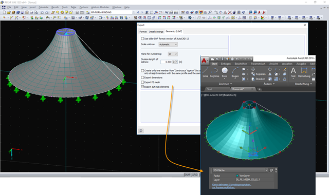
The DXF interface in RFEM now exports a 3DFACE element in the DXF file for each FE mesh cell of the exported structure. The 3DFACE element is detected by AutoCAD during import, for example, and can be displayed as a surface in the graphic. Different visual styles help display the 3DFACE surfaces in a desired view.

With RFEM 5.06 and RSTAB 8.06, the examples and help files for programming the COM interface are not only available on the Internet, they are also included in the installation. To find them, look for the "SDK" folder in the project directory (usually C:\Users\Public\Documents\Dlubal).
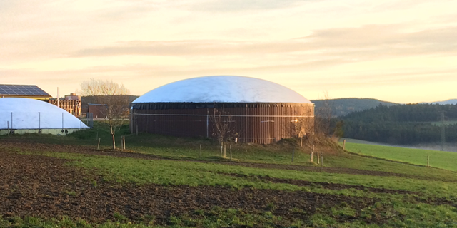
Due to the structural efficiency and economic benefits, dome-shaped roofs are frequently used for storehouses or stadiums. Even if the dome has the corresponding geometrical shape, it is not easy to estimate wind loads due to the Reynolds number effect. The external pressure coefficients (cpe) depend on the Reynolds numbers and on the slenderness of the structure. EN 1991‑1‑4 [1] can help you to estimate the wind loads on a dome. Based on this, the following article explains how to define a wind load in RFEM. Wind loads of the structure shown in Image 01 can be divided as follows: Wind Load on Wall, Wind Load on Dome.
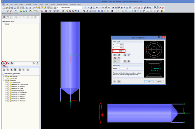
If you consider rotating the structure shown in the figure around the global Y‑axis, this might be not straightforward. In order to achieve better handling, the axis is always locked in the direction of your view. In the case of very high structures, it may be helpful to rotate the view about 90 degrees in the viewing direction.
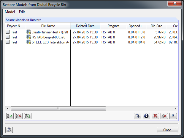
The integrated project manager helps you to organize design files of Dlubal Software programs. For this, a link is created between an existing project folder on the hard drive and the Project Manager. If you want to delete a project created in the Project Manager, there are two methods.
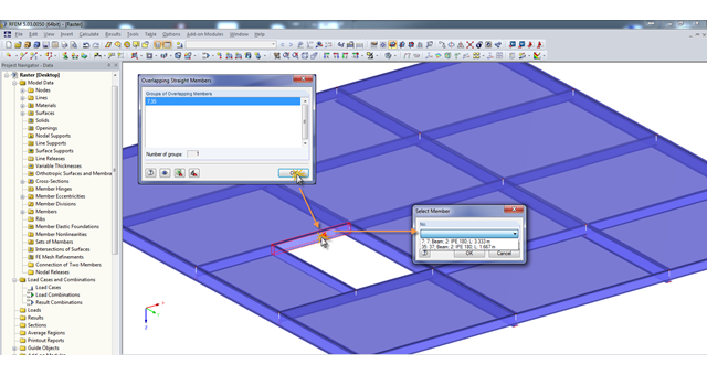
A modell check allows you to find overlapping members, among other things. However, this targeted selection could cause some minor problems. Therefore, there is a selection window now available, which appears when you click on one of the elements. This appears by clicking on one of the elements. Additional information helps you to select the correct member.
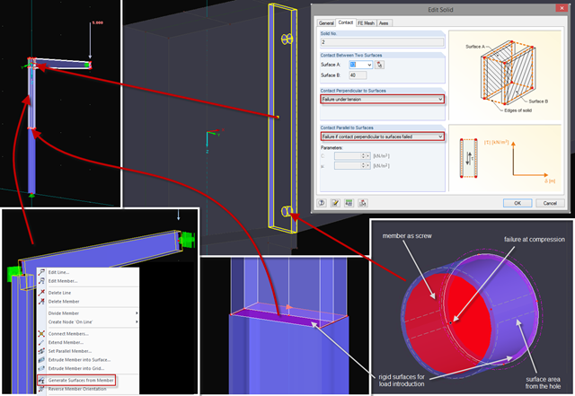
Sometimes, a detailed examination is needed of problematic areas of a joint or the stiffness of a frame joint. The following tips can help you with this. As an example, a frame joint was modeled using RF‑FRAME‑JOINT Pro and members, and used as a basis.